
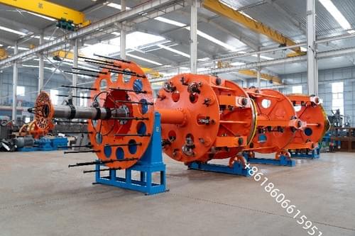
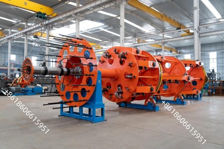
EV Cable ( Charging Pile Cable )Stranding Machine CLY1250/6+630/6
Model: CLY1250/6+630/6
Dual system of mechanical and magnetic tension.
EV Cable ( Charging Pile Cable )Stranding Machine CLY1250/6+630/6
1. Machine concept and scope
A planetary stranding machine for charging pile cables builds the conductor by rotating multiple carriers (carriers or bobbins) around a central axis while feeding element wires, enabling compact, round, and dimensionally stable multi-layer constructions. It is widely used for AC/DC EV charging pile conductors(e.g., up to 5–500 mm²typical range, expandable), and can be extended with downstream laying-up, filling, tape wrapping, and take‑up to form complete cable cores or cords ready for insulation/extrusion. The planetary method is preferred when tight diameter control, high strand count, and uniform lay are required for flexible, high‑cycle charging applications.
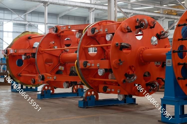
2. Key specifications and performance
Typical machine scale and performance envelope (representative cradle/planetary laying‑up line):
Bobbin sizes: 630 / 800 / 1000 / 1250 / 1600 mm
Single‑wire diameter: φ5–35 mm(model‑dependent)
Max stranded conductor OD: φ30–φ80 mm(model‑dependent)
Lay pitch: 50–5176 mm(model‑dependent)
Capstan diameter: 1000–2500 mm
Max haul‑off force: 10–25 t
Max haul‑off linear speed: 21–60 m/min
Motor power (exemplar 630 model): 18.5 kW; larger frames scale accordingly
Features often include: retreat‑spiralling / non‑retreat‑spiralling, pre‑spiralling (manual/automatic), and axle/non‑axletake‑up
Central height: 1000 mm; delivery lead time: 100–110 days(example)
These ranges reflect a production‑proven line platform; actual build size, speed, and power are selected to match target conductor OD, lay length, and required output.
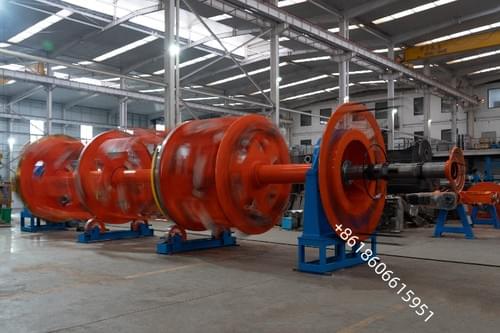
3. Process line composition and control
Line modules commonly integrated:
Central pay‑off, frame host, assemble holder, taping device, armouring device, meter counter, traction device, take‑up and traverse, transmission and electric control system
Control and quality features commonly implemented:
Laser laser diameter gaugingon each incoming element wire to reject undersized/oversized feedstock before stranding
Interlocked rejection and manual/automatic handling of nonconforming wires to prevent structural defects and overheating in service
Servo‑driven lay control for lay lengthaccuracy and repeatability across shifts
These measures ensure uniform strand distribution, consistent diameter, and mechanical integrity of the stranded core.
4. Cable design targets and material choices
Performance envelope for EV charging pile cables (illustrative):
Voltage: AC 220/440 Vor 450/750 V; test: 2000 V/2500 V
Operating temp.: fixed −40 to +105°C; occasional movement −30 to +105°C.
5.Electrical Control
The power supply of this machine is: three-phase five-wire system, 380V, 60Hz, 110kw total
The whole machine linkage adopts field bus control, and uses PLC and touch screen to coordinate the operation of each part of the motor.
Various process parameters can be set, modified and displayed on the touch screen.
This machine is equipped with the following protection links
Fault alarm of each speed regulating device;
Cable overtravel protection;
Protective cover safety protection;
Tape break protection;
Air underpressure protection
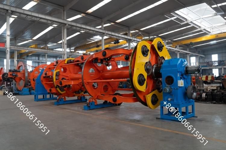
6.Safety protection devices
Main cage: Single side wall safety net
Taping machine: Fully enclosed box sliding door safety cover

7. Sizing and procurement guidance
• Define targets: target conductor cross‑section(s), strand count/shape (e.g., sector, round), lay length/pitch, target OD tolerance, required output (m/min), and whether retreat‑spiralling is needed.
• Select machine scale: match bobbin size, haul‑off force, and lay pitch range to the conductor OD and lay; ensure sufficient power headroom for the selected speed/tension window.
• Integrate downstream: add filling, tape wrapping, armouring, and take‑up/traverse as needed for cord or core finishing prior to insulation/extrusion.
• Implement quality control: include laser diameter gauges on feeders, interlocks, and traceable meter counting; define acceptance criteria for diameter, lay, and conductor uniformity.
• Schedule and logistics: plan for factory acceptance testing (FAT), tooling (paysoffs, bobbins, traverses), commissioning, and spares; typical lead times can be ~10–12 weeks for standard builds, longer for high‑torque or specialized tooling.
